
MIDILLI STL Generator is a free and versatile command-line tool for creating STL files to prepare box-shaped parts with the help of free and open-source OpenSCAD. It supports circular drill holes, rectangular cutouts, text engraving, and precise dimensions in metric units. The generated STL files can be opened in 3D viewers, or can directly be used in slicers to be printed via 3D Printers.
Derived from the in-house MIDILLI Tech Automation Suite, this tool is a simplified yet robust solution.
It is offered free for non-commercial use. You can find the full license details here.
Please choose a topic from below to read.
Features
- Box Creation:
- Generate rectangular shapes with up to six sides to form a complete box structures.
- Option to omit any side during box design.
- Option to use the sizing for the inner volume or the outer volume.
- Customizable Cutouts:
- Create holes or rectangular cutouts (also called components) on specific sides of the box with precise locations.
- Create screw holes on top or bottom side with the given screw diameter.
- Component Rotation:
- Rotate components to any specified angle in degrees.
- Text Engraving:
- Create text engravings with adjustable font sizes, rotation (aligned with component rotation), and customizable engraving depth.
- Recess Support:
- Create flush surfaces with custom dimensions that prevent movement of e.g., button caps and improve functionality.
- Create recesses for screw heads*.
- Single or Multiple Sides:
- Separate sides of the box, or create as a single part.
- Material Thickness:
- Adjust material thickness for accurate cuts and fits.
- Box Sizing:
- Automatically adjust box sizes for inner or outer edges, depending on user preference.
- Create OpenSCAD projects to enable fine-tuning.
How does it work?
The tool takes a JSON file as input (example below) and generates STL files for up to six sides of a box, with each side containing its own drill cutouts, and recesses. These pieces can then be assembled to construct a 3D shape, or a single part can be generated.
The exported .stl files must be used with a slicer software (or a 3D Printer software) to complete the task.
Warning: Operating 3D printers requires a safe environment to prevent exposure to hot surfaces, moving parts, and emitted fumes. Never place your hands near the moving parts or the print head. Always ensure proper ventilation, wear safety goggles, and use hearing protection if necessary. Additionally, perform a simulation to ensure the print job does not attempt to print in restricted or potentially dangerous areas.Download
By downloading our free software, you agree to the license conditions.
Version History
- 1.1.0 (01.04.2025):
- Added text engraving option with custom rotation, font size, and engraving depth.
- 1.0.1 (08.02.2025):
- Replaced
heightwithlengthin JSON to avoid confusion.
- Replaced
- 1.0.0 (22.01.2025):
- Initial version.
Quick Usage
[Top]
Download the ZIP file and extract to a location. Copy the Example JSON file below and save it as test.json using a simple text editor. To keep the things simple, save it at the same location as the executable.
Example JSON file
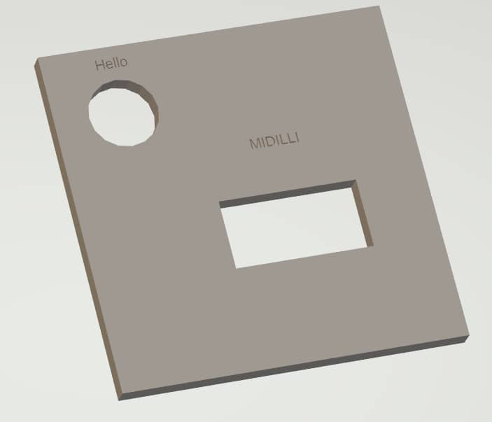
The following file generates all six sides for MyPart, placing one hole and one rectangle cutout on the Top side. The top size of the box is 5×5 cm and the components are placed at (x = 1, y = 1) and (x = 3, y = 3) respectively. The visible sizes of the components are the same as drill sizes.
{
	"Generic": {
		"width": 5.0,
		"length": 5.0
	},
	"MyPart_Top": {
		"myRoundComponent#1": {
			"location_x": 1,
			"location_y": 1,
			"drill_diameter": 1,
			"call_name": "Hello",
            "visible_diameter": 1,
			"rotation": 0
		},
		"myRectangleComponent#1": {
			"location_x": 3,
			"location_y": 3,
			"drill_width": 2,
			"drill_length": 1,
			"call_name": "MIDILLI",
			"visible_width" : 2,
			"visible_length" : 1,
			"rotation": 0
		}
	},
	"MyPart_Bottom": {

	},
	"MyPart_Back": {

	},
	"MyPart_Front": {

	},
	"MyPart_Left": {

	},
	"MyPart_Right": {

	}
}
Depending on the command-line options, the other sides of the part will be created using different sizing. Read Coordinate system and effect of sizing parameters for more on different results of the arguments.
Note: JSON syntax is very strict. Ensure that the last line before each '}' does not end with a comma, while all other lines should. Use an online validation tool to confirm correctness.
Command line
Assuming that the JSON file is stored at the same location as the executable file, open a command window (Command Prompt, or PowerShell), then execute the following command:
Note: The following command requires installation of the free and open-source OpenSCAD software.
.\STLGenerator.exe --json-file .\test.json --output-directory .
 --material-thickness 3 --box-height-3d 30 --single-part --separate-top
You will be provided with an output showing the current settings as following:
~~~~~ Settings ~~~~~
Single part: Yes
Separate top: Yes
Separate bottom: No
Screw diameter: 0 mm
Screw head height: 0 mm
Screw head diameter: 0 mm
Screw extra margin: 0 mm
Outer sizing enabled: No
Material thickness: 3 mm
Box height in 3D: 30 mm
Recess depth: 0 mm
Draw text: Yes
Font size: 8 px
Text depth: 1 mm
OpenSCAD path: C:\\Progra~1\\OpenSCAD\\openscad.exe
Keep OpenSCAD files at the end: No
Create only OpenSCAD files: No
Verbose enabled: No
Each setting on the console output can be customized with command line arguments.
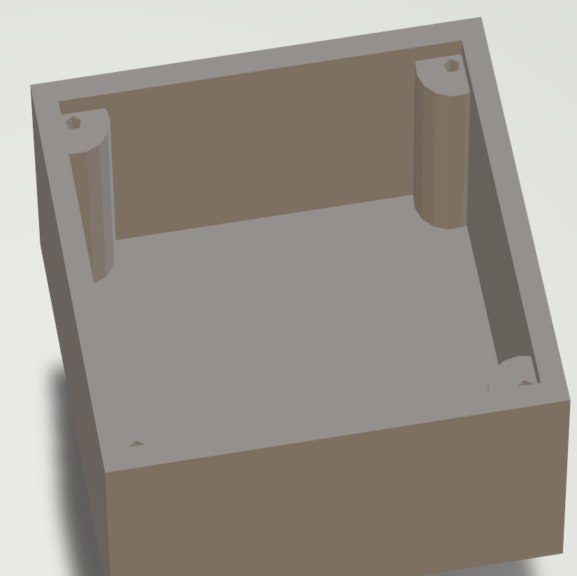
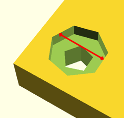
After completion, 6 files starting with MyPart_ and ending with .stl, test_merged.stl, and MyPart_Top.scad file will be visible under test directory. Opening MyPart_Top.stl and test_merged.stl in a program which can view STL files should display results similar to the following:
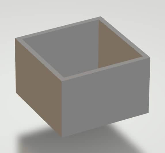
From this point, you can use your slicer software to start printing.
Coordinate system and effects of sizing parameters
[Top]
Read more on the following page:
Tip: If you want the overall size to be exactly as you specify in the JSON file, use the --outer-sizing option. If you want the usable inner area to be the same as you define, leave it as default.Detailed Usage
[Top]
Below, the detailed usage of the tool and the standard JSON project file will be explained.
Command line arguments
If the program is executed with -h or --help option, the following quick help will be displayed:
  STLGenerator.exe [OPTION...]

  -j, --json-file arg           Project JSON file
  -o, --output-directory arg    Output directory
  -t, --material-thickness arg  Material thickness in mm
  -b, --box-height-3d arg       Box height in 3D in mm
  -s, --single-part             Merge all STL files to construct a 3D box.
                                Use --separate-top and/or --separate-bottom
                                to separate the sides
  -p, --separate-top            Do not combine the top side with the other
                                sides when using the --single-part option
  -m, --separate-bottom         Do not combine the bottom side with the
                                other sides when using the --single-part
                                option
  -w, --screw-size arg          Screw diameter in mm (default: 0)
  -d, --screw-head-height arg   Screw head height in mm (default: 0)
  -a, --screw-head-diameter arg
                                Screw head diameter in mm (default: 0)
  -e, --screw-extra-margin arg  Screw extra margin in mm (default: 0)
  -z, --outer-sizing            Box sizes are for outside borders (inner
                                area will be smaller)
  -r, --recess-depth arg        The depth of recess in mm (Default: no
                                recess) (default: 0)
  -x, --draw-text               Whether to draw text (default: true)
  -f, --font-size arg           Font size to draw in px (default: 8)
  -q, --text-depth arg          Depth to engrave text in mm (default: 1)
  -c, --openscad-path arg       Path to OpenSCAD executable (default:
                                C:\\Progra~1\\OpenSCAD\\openscad.exe)
  -k, --keep-project-files      Do not delete OpenSCAD files at the end
  -n, --only-project            Create only OpenSCAD files, do not create
                                STL files
  -v, --verbose                 Verbose output
  -h, --help                    Print this help and exit
Both short and long versions of the arguments can be used.
The arguments -j, -o, -t, and -b are mandatory. Other arguments have default values as mentioned above. To set an argument to false, use the long version and assign the value false. For example, to disable outline cut, use --only-project=false. Similarly, for verbose, use either -v or --verbose. Argument values can be provided with a space or an equal sign if long versions are used. For instance, both --json-file test.json and --json-file=test.json are valid usage. For short versions, only space allowed, e.g., -b 30.
--json-file
A valid path to JSON file to be used as input. Can be a relative path (starting from the working directory) or an absolute path.
--output-directory
The directory to write the output files to. Using . (dot) will use the current working directory. The final files will be written into a new folder having the name of the --json-file.
--material-thickness
This value is used to calculate the depth required for creating holes for components and/or screws. The value is in millimeters (mm).
Additionally, this value is used to determine the dimensions of the left, right, front, and bottom sides (if enabled) based on whether the --outer-sizing parameter is active. See Coordinate system and effects of sizing parameters for more info.
--box-height-3d
The height of the box in millimeters (mm). If --outer-sizing is used, this will be the outer height of the box. Otherwise, it is the inner height of the box.
--single-part
Merges all sides into a single file (.scad or .stl) to construct a complete 3D box. To separate top or bottom, use --separate-top and/or --separate-bottom respectively.
Default: false
--separate-top
Separate top side of the box from the rest of the sides and save it as a separate file if --single-part option is used. This will also leave the _Top.scad project file in the folder.
--separate-bottom
Separate bottom side of the box from the rest of the sides and save it as a separate file if --single-part option is used. This will also leave the _Bottom.scad project file in the folder.
--screw-size
Screw hole diameter to be drawn as hole in millimeters (mm) on the top and/or bottom side of the box. Needs at least --separate-top or --separate-bottom to be used. Otherwise no screw holes will be generated.
This will also generate 4 cylindrical supports to fix the screws.

Default: 0 mm, no screws.

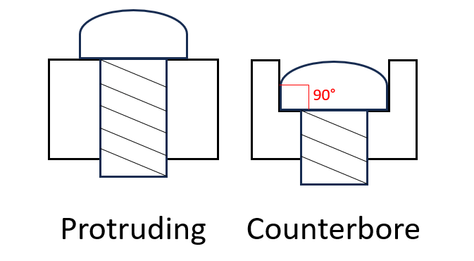
--screw-head-height
The depth of the screw-head to create counterbore/recessed screws given in millimeters (mm).
Default: 0 mm, protruding screw head.
--screw-head-diameter
If the screws must be counterbore/recessed, any value given in millimeters (mm) (preferably greater than --screw-size) will create a circular shape to bury the head.
Default: 0 mm, protruding screw head.
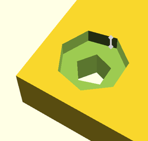
The images below show how --screw-head-diameter and --screw-head-height affect the creation of screw head related recesses.
--screw-extra-margin
By default, screws are added at the four corners of the top and/or bottom side of the box, leaving a margin of --material-thickness from the sides. If an additional margin is desired, any value given in millimeters (mm) will increase this gap.
Default: 0 mm, no additional margin.

--outer-sizing
If used, the sizes defined in the JSON file as well as the --material-thickness and --box-height-3d arguments will be used to create the outer volume with the given dimensions. Otherwise, these values will be used to create the inner volume with the given dimensions.
Default: false, use inner dimensions.
--recess-depth
The depth of the recess for components in millimeters (mm).
Recesses also take the sizing from visible_diameter (priority) or visible_width and visible_height properties. Recesses may be helpful to have slightly lowered shapes to e.g., stabilize or limit the movement of button caps. This value does not change the behavior of the screw head recess (See --screw-head-height).
Default: 0 mm, no recess for the components
--draw-text
Whether to draw texts defined in the JSON file with call_name. Font size can be specified with silkscreen_font_size or with --font-size argument.
Default: true, draw text.
--font-size
The size of the font in pixels (px). The value is converted to OpenSCAD size value using the formula in its manual. This is only effective, if no silkscreen_font_size found for a call_name.
Default: 8 px.
--text-depth
The engraving depth for the text in millimeters (mm). If greater than material-thickness, material-thickness will be used. This value is used for all call_names.
Default: 1 mm.
--openscad-path
Path to OpenSCAD executable to convert .scad files to .stl files. Requires free and open-source OpenSCAD to be installed separately.
Default: C:\Program Files\OpenSCAD\openscad.exe
--keep-project-files
Keeps the OpenSCAD files (.scad files) after conversion to STL.
Default: false, remove .scad files after conversion to STL.
--only-project
Only creates .scad files and does not start STL conversion. This is useful e.g., to work on the files using OpenSCAD for fine-tuning or modifications.
--verbose
Shows more information during project creation and outputs of the OpenSCAD software during STL conversion.
--help
Shows the quick help with the list of arguments and their short descriptions.
JSON File
See the definition on this page: MIDILLI JSON File Definition.